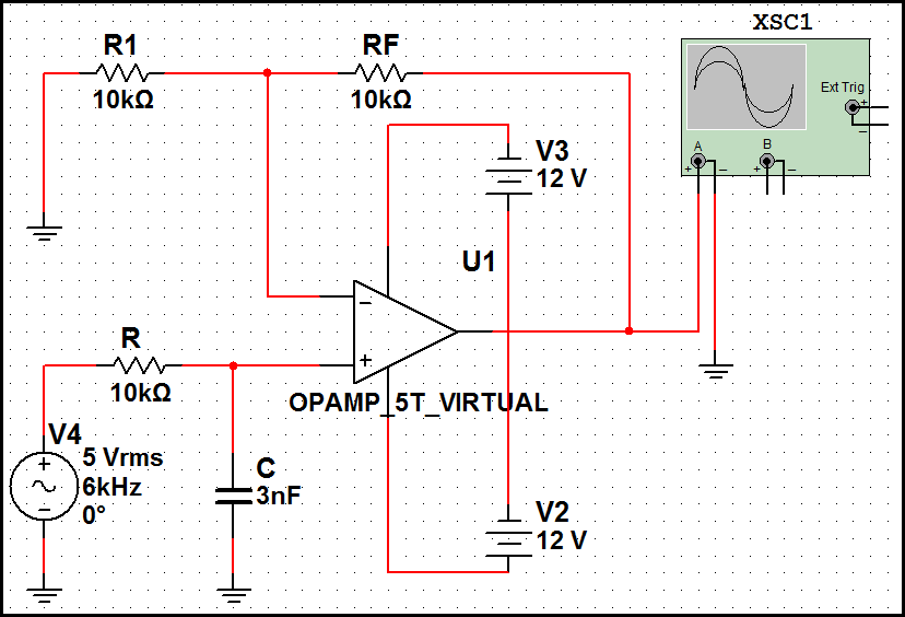
First Order Low Pass Filter Circuit Diagram
Filter pass low order circuit diagram nd fig First order low-pass active filter: the circuit schematic diagram and Ua741 low pass filter circuit 10khz
Types of Passive Low Pass Filters - RL and RC Passive Filters
First order low pass filter Low pass filter : circuit, types, calculators & its applications Pass low filters why rc frequency network khz electrical
Active low pass filter
Why do the orders of hi/low pass filters go in 6 db increments?Filter order second pass circuit low filters frequency inverting lpf 2nd differential amplifier emg butterworth off signal graph active diagram Simple low-pass filter circuit diagramTransfer function.
Butterworth electroschematicsLow pass filter : circuit, types, calculators & its applications Inductor passiveFilter circuit pass low diagram simple audio filters passive basic voltage seekic ripple schematics gr next nonlinear.

Lpf active
First-order butterworth active low-pass filter circuitFourth-order chebyshev low-pass filter circuit Filter pass low order first schematic circuit resistor circuitlab created using schematics stack1st order low pass filter (inverting).
Passive circuits☑ high pass filter second order Types of passive low pass filtersPass filter low active circuit experiment construct.

Pass filter order low passive second 2nd frequency cutoff function transfer schematic circuit two filters electrical deriving consisting circuitlab created
Pass filter low order inverting 1st circuit first circuitlab descriptionCircuit ua741 filter pass 10khz circuits electronic schematics Pass low filter rc passive types filters rl capacitor resistor output connected shown across taken below figure series.
.


